My First Shitty Add On
So with DEF CON 31 (2023) around the corner I thought it was a good opportunity to finally learn KiCad and build a shitty Add On (SAO). Being a bit short of time, and a bit short of ideas I thought a version of the Logo of the company I work for would be a good starting point.
The Plan
The following criteria were set:
- Keep it simple
- Keep it cheap
So no clever tricks, just a window in the copper and solder mask layers to act as a light mask, and back-lit LEDs to illuminate the design.

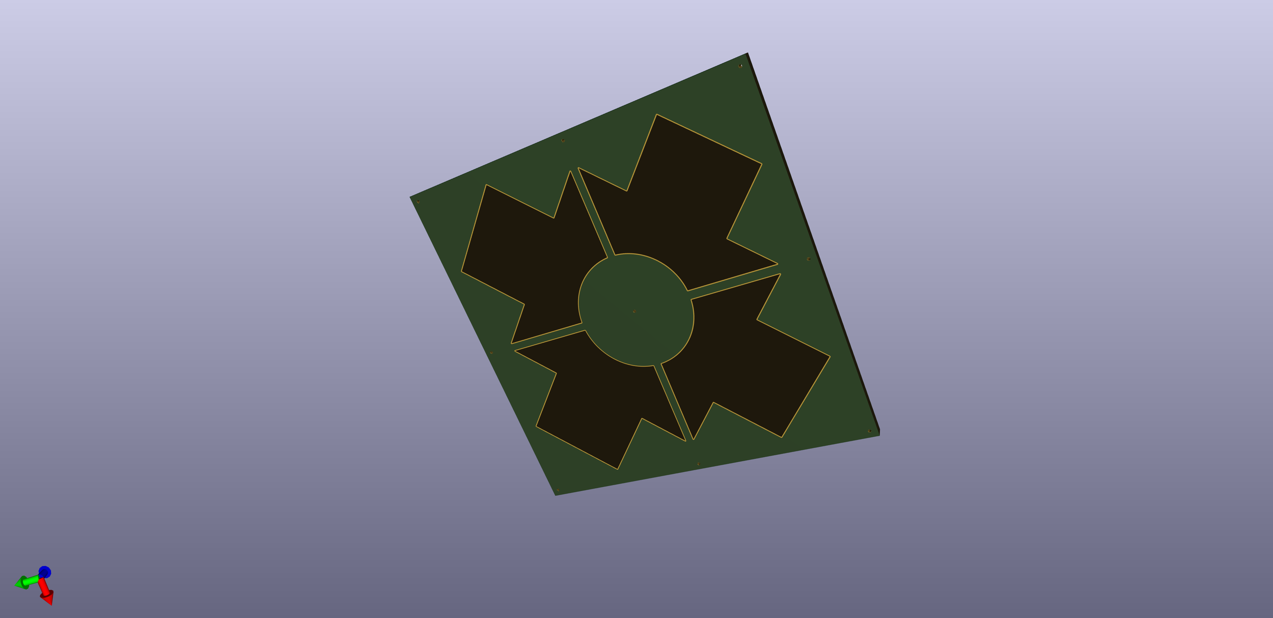
badge plan
After some searching of available components with the manufacturer I was planning to use (JLCPCB) it became clear that rear firing LEDs were going to be too expensive, but side firing LEDs were much cheaper. So a revised plan using these and “light-pipes” / diffuser was decided on (more on this later).
Schematic SAO3
As this schematic shows, there really isn’t much to this board. Just the connector the LEDs and their corresponding current limiting resistors.

schematic
The board
This is what KiCad thinks the boards should look like.
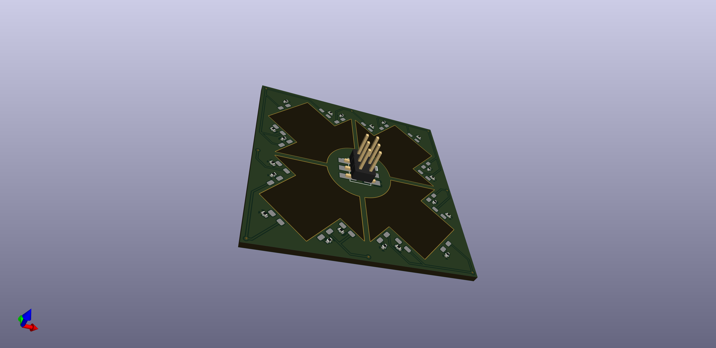
And here is a terrible 3D render of the board… sans texturing. It should rotate if you drag on it, but your mileage might vary. I might come back and fix this view later, but I have already spent too much time on getting the JavaScript for this view to work to not leave it in.
Production
The Bill of Materials (BoM), Gerbers and Centroid (CPL) were sent over to JLCPCB (thanks Omer for help with this step). A few tweaks were made with JLCPCB to correct the component alignment. Then money exchanged hands and the waiting commenced. This step was easier than I expected but having someone show me the ropes really was helpful. I decided to go with fully manufactured boards with JLCPCB doing all the work
The board arrive
Roughly one week later a box from FedEx arrived, and I got to testing the boards.
Here you can see the board all lit up, I am not super happy with the brightness around the centre, but there should be enough space to add four more LEDs here
board lit
Here you can see the “light-pipe” I previously mentioned. The technical solution of globs of hot snot.
board light pipe
The F*ck up
So there was one small, tiny issue, with this board. The power pins are reversed. ☹. It’s not the end of the world because I was going to run another spin of this board with the extra central LEDs. Testing has also shown that the LEDs are drawing quite a bit of current so slightly higher value resistors are going to be used in the next version.
I also didn’t plan around the manufacturing holes that JLCPCB require, they are not super obvious, but you can see them in the picture above. So in the next spin I will try and minimise these too.
What’s Next
I might update this post with more details after I finish the re-spin… Or I might forget.
I only went and actually made a second post!